Q&A
1. Input condition
What happen if high/low input frequency is applied?
There are 50Hz and 60Hz of the commercial rated input frequency. Most of COSEL's power supply must be used at 47 to 63Hz as specs. However, the electrical characteristic like the output voltage and so on does not depend on the change of the input frequency very much. Our products applying to the safety agency approval must be operated at the rated input frequency, if you need the safety agency approval.
1. High input frequency
There are two types of the input frequency spec in COSEL's products. One is 47 to 63Hz, and the other is 47 to 440Hz. Because the loss of the capacitor and rectifier diode is increased and these make efficiency and power factor low, the power supply should not be used at the input frequency exceeding the spec.
2. Low input frequency
If the power supply is used at the input frequency that is lower than the rated, because charging time is longer than the normal and the input capacitor can not enough charge, the output voltage might be decreased.
What is harmful effect of input line impedance?
1. Summary
If the input line impedance for the DC/DC converter is high, the input voltage might get fluctuation, then it causes the output voltage unstable.
2. Input voltage fluctuation
If the inductance value is too much (see Fig. 2.1), the resonance circuit is composed by inductor L and capacitor C, and then it makes the input voltage change.
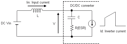
Fig. 2.1 The input line circuit
Please refer to the following for the change level of the input voltage.
In the circuit as shown in Fig. 2.1, the energy of inductor and capacitor is shown as the following.Energy of inductor El : 1 / 2 x L x rI2
Energy of capacitor Ec : 1 / 2 x C x rV2In the resonance circuit, energy of inductor and energy of capacitor are same. Therefore, the input voltage fluctuation (rV) is shown as the following.
rV = √(L x rI2 / C) -------(1)
3. Proposed measures for the input voltage fluctuation
Please refer to Table 3.1 for the measures to inhibit the input voltage fluctuation derived by the formula (1).
Table 3.1 Proposed measures for the input voltage fluctuation No. Measure Concrete measures 1 Decrease L Make input line short and use thick cable 2 Increase C Add capacitor to DC/DC converter input 3 Reduce I Reduce the output current What is harmful effect of out of input voltage spec operation?
The power supply has a spec of the input voltage range. If it is operated outside the spec of the input voltage range, the problem as the following may be caused. Therefore, it is not allowed to be operated outside the spec of the input voltage range.
1. The case that is operated at lower than the spec of the input voltage range
Basically, the power supply can not be operated at lower than the spec of the input voltage range. Even if the power supply work, the power supply may get broken because the input current that is increased may exceed the rated current of internal components.
2. The case that is operated at higher than the spec of the input voltage range
If the power supply is operated at higher than the spec of the input voltage range, it may get broken because the voltage that is applied to some internal components may exceed the rated voltage of them.
3. AC132V - AC170V input with input voltage selector type
(1) Auto-selectable
The internal circuit detects the input voltage, and changes the input voltage selector. The input voltage selector is changed to the voltage double rectifier when the input voltage is AC85V - AC132V, and it is changed to full wave rectifier when the input voltage is AC170V - AC264V. If the input voltage is AC132V to AC170V, the operation of this selector gets unstable. Therefore, the power supply may not be operated regularly if it is operated at AC132V - AC170V of the input voltage.
(2) User-selectable
If the input voltage selector is AC100V type, it means that it is same condition as item 2. And, if the selector is AC200V type, it means that it is same condition as item 1. Therefore, please avoid operating it at AC132V - AC170V of the input voltage.
Is it possible to use UPS as input source?
1. The waveform of the input voltage
The waveform of the AC input voltage is the sine wave. However, the input voltage is rectangular wave when UPS is used. Please refer to Fig. 1.1. If the input voltage is the rectangular wave, please consider the voltage operating the power supply and the rated current of the capacitor between the input line.

Fig. 1.1 The input voltage of rectangular wave
2. The voltage operating the power supply
The power supply makes the DC voltage in which value is near the crest value of AC voltage by rectifying AC voltage for operation. The peak value of the input voltage whose value is the sine wave times the square root of two need to be applied to the power supply. Therefore, the input voltage range is shown as the following when UPS is used.
For example;
AC85V - AC 132V
Sine wave→
120V - 186V (peak value)
Rectangular wave(UPS)3. The rated current of the capacitor between the input line
If the input voltage is the rectangular wave, the ripple current of the capacitor between the input line is increased than the case that the sine waveform is applied. Therefore the ripple current should be considered whether it is smaller than the rated current of the capacitor. The ripple current depends on the voltage gradient and the kind of the power supply.
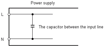
Fig. 3.1 The input circuit
If you are planning to use UPS in your system, please contact us in advance.
Is it allowed to apply DC voltage to AC-DC unit?
1. The operation in DC input voltage
In input circuit of switch mode power suppies, basically once AC input voltage is rectified and is converted to DC voltage. Therefore, they could be operated with DC voltage. However input voltage selector type is not allowed to be operated with DC voltage.
Since the rectified voltage is smoothed by capacitor, it is required to apply DC voltage in which value is equal to the crest value of AC voltage. Therefore, when they are operated with DC voltage, the rated AC voltage times the square root of two (= AC voltage x √2) needs to be applied. Please refer to the DC input voltage range in COSEL catalog.
2. The wiring for DC input
2.1 The outline
Because there is the full-wave rectifier circuit, the positive / negative voltage can be applied to either terminal of the input.
2.2 The recommended wiring
The positive voltage can be applied to either terminal of the input, but COSEL recommend that the positive voltage is applied to the terminal AC(L) which has fuse. Please refer to Fig. 2.1.
When DC input is applied to AC-DC power supplies, please put DC rated fuse on the input line for protection at the power supplies failure.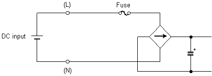
Fig. 2.1 The recommended wiring for DC input
2.3 Internal fuse
The most of all power supplies have AC rated fuse. Please add DC rated fuse on the input line, because AC rated fuse wouldn't work safely with DC input at abnormal condition.
2.4 Condition of acceptability for safety approval
Most of Universal input type AC-DC power supplies are certified under the input voltage condition of "100VAC-240VAC(50/60Hz)".
Please see instruction manual of each product for details.
Therefore, safety approvals are not applied to DC input condition except some products certified with DC input.What is meaning of (L) and (N) on AC terminal?
There are two different name, L (Live) and N (Neutral) on the AC input terminal. Please refer to Fig. 1 for the wiring of the AC input. The terminal L must be connected to the unearthed conductive part of AC main supply and the terminal N must be connected to the earthed conductive part of AC main supply, to apply the safety agency approval. This purpose is protection by a blowout fuse from electric shock by earth fault.
Also, the terminal FG needs to be connected to the earth to protect from electric shock and noise interference. Even if the terminal L and the terminal N is connected to another side or the terminal FG is not connected to the earth, then the power supply might not get broken and might not change its characteristic.
Even if terminal L and N are connected oppositely, power supply operates normally. However, please note that the conductive part would be kept under the earthing fault condition. Please note that conducted emission and ripple noise characteristics would be changed when FG is not connected to ground.
Most of AC-DC power supplies are classified as CLASS Ⅰ equipment in safety approval requirement, therefore FG terminal should be connected to the safety ground of the equipment.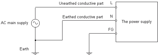
Fig.1 The wiring of the AC input
Is it possible to apply 400Hz input to AC-DC unit?
Generally, the commercial frequency is 50Hz or 60Hz. However, the voltage which is from dynamo, its frequency is around 400Hz.
There are two types of the input frequency spec in COSEL's products. One is 47 to 63Hz, and the other is 47 to 440Hz.If the input voltage with high frequency is applied to the power supply in which spec is 47 to 440Hz, the leakage current could increase. However the operation of the power supply is normal.
The input voltage with high frequency can not be applied to the power supply in which spec is 47 to 63Hz, because there is possibility that the problems as the following occur. Incidentally, the spec of PFC (Power Factor Correction) circuit built-in power supply is 47 to 63Hz.- Power factor decreases
- Produce a sound from choke coil
- The input current increases because the resonance occurs in the internal circuit
- The leakage current increases
If the power supply that has the PFC circuit is used at 400Hz of input frequency, it is required to consider the behavior of characteristics. If you need to use the power supply as above, please contact us.
How to use Three-phase EMI Filter to Single-phase input?
Our Three-phase/Three-wire type EMI Filter can be used for Single-phase input.
Attenuation characteristics at three-phase and single-phase are shown below (ex. TAC-30-683), and confirmed that there is no big difference between them.
Rated input voltage of Three-phase EMI filter is AC500V, but it can be used for AC100V or AC200V input as well.
Three-phase input Attenuation Characteristics
(Measurement diagram: See Fig.1 and Fig.2)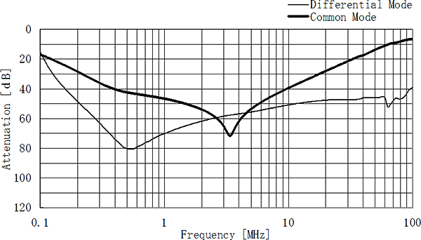
Single-phase input Attenuation Characteristics
(Measurement diagram: See Fig.3 and Fig.4)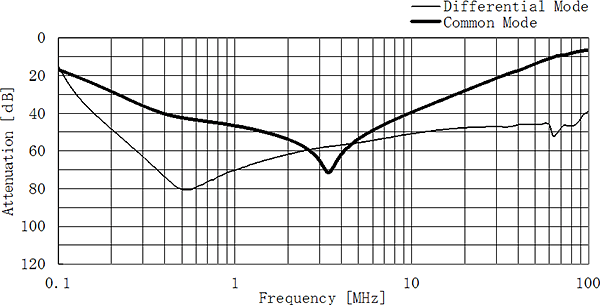
Please evaluate adequately in your equipment before use.
Three-phase input attenuation measurement diagram
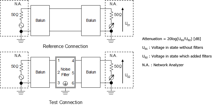
Fig.1 Differential mode attenuation measurement diagram
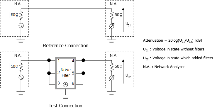
Fig.2 Common mode attenuation measurement diagram
Single-phase input attenuation measurement diagram
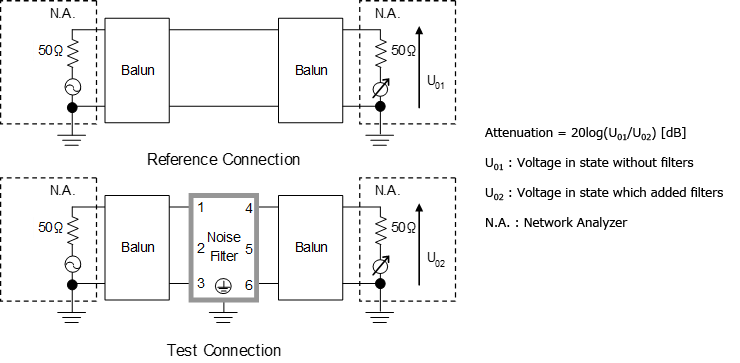
Fig.3 Differential mode attenuation measurement diagram
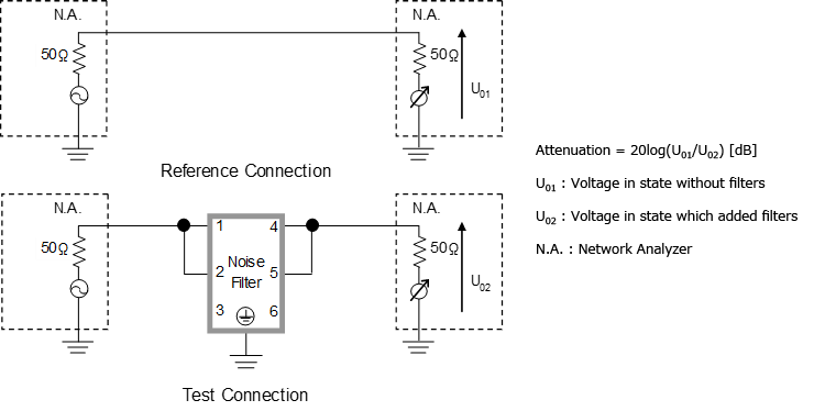
Fig.4 Common mode attenuation measurement diagram
2. Load condition
How can pulse/peak current be drawn?
The pulse load means changing the current like the pulse. For example, motor for printer, print head, LED display, HDD, FDD and so on. There is no problem if the peak current is the rated current or less.
[ How to draw pulse/peak current ]
Basically, the power supply can not flow the output current which exceeds the rated current continuously. However, it is possible to flow the peak current when peak current time is short.(1) The case that the peak current time is several us
The peak current will be able to be flowed from the internal capacitor of the power supply. Please contact us about detail.
(2) The case that the peak current time is from several us to several ms
It will be possible to flow the peak current if the external capacitor is installed. The capacitance of the external capacitor can be calculated by the following formula.

- *)Please consider the rated ripple current of the external capacitor.
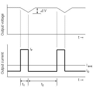
- *)Output current should meet the following.

(3) The case that the peak current time is several ms or more
There are power supplies that can flow the peak current which is approximately 1.5 times for 10 seconds. However, the average current should be the rated current or less. Please contact us about detail.
How to read derating curve?
1.Meaning of derating curve
The available output current of the power supply depends on the ambient temperature and mounting method. In addition, the available output current changes by the input voltage depending on a product. This condition is shown on the instruction manual and specification sheet as a derating curve. Please refer to the Fig.1.1 and Fig.1.2 for the example of derating curve.
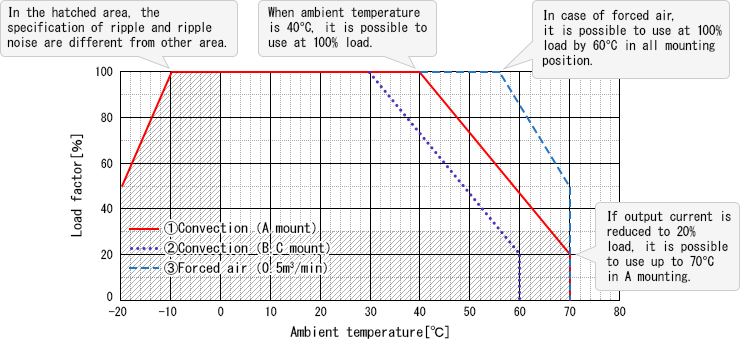
Fig.1.1 Example of Ambient temperature derating curve
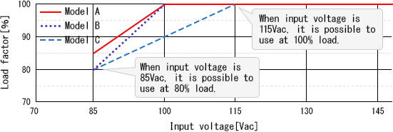
Fig.1.2 Example of Input voltage derating curve
2.How to calculate if two derating curves shall be considered?
In case of two derating curves should be considered, available load factor can be calculated by multiplying both derating ratios.
(Available load factor) = (Input voltage derating) x (Ambient temperature derating)
Example
Model Model C (on Fig.1.2) Input voltage 100Vac Ambient temp 40℃ Mounting B mounting Cooling Convection Calculation
Ambient temperature derating = 73% Input voltage derating = 90% ↓
Available load factor = 73% x 90%
= 65.7%- ※In the case of multiple supply, the ambient temperature derating must be applied to all output current.
Why does audible sound occur with pulse load?
1. Cause of the sound
The pulse load like the motor and the indicator generally will produce the sound. In most of the case, when the frequency of the pulse load is audio frequency which is a few kHz to 20kHz, the sound is produced. The part producing the sound would be choke coil. The vibration of core by the magnetic field produced by the pulse current flowing through the coil produces the sound. Please refer to the following for the mechanism of producing the sound. If the current flows through the magnetic body like the core, the core is magnetized. And then, if the current changes, the magnetostriction is generated. It is the phenomenon that the magnetic body expands and contracts. The air vibrates by this phenomenon, and makes a sound. Because there is no nick, crack and the change of the magnetic characteristic by generating the magnetostriction, because this is common phenomenon to the magnetic body, there is no problem in the electric characteristic.
2. Solution
Even if there is a sound from the power supply, it is no problem to the electric characteristic. Besides, the sound from the power supply will be reduced if external LC filter is assembled to the output of the power supply.
What is influence of back electromotive force from motor on PSU?
In the case that the load is the motor, the current that is several times more than its rated current flows when the motor starts up. Also, the back electromotive force( E = -L x (di/dt) ) is generated when the motor stops.
1. Peak current by starting the motor
The peak current that is several times more than its rated current flows when the motor starts up. If this peak current is bigger than the rated current of the power supply, the output voltage of the power supply is decreased by activating the overcurrent protection . Then, because the voltage applying to the motor is decreased, the maximum torque can not be produced. Incidentally, this maximum torque is same as the torque using at the rated condition. If the maximum torque is needed when the motor starts up, the power supply in which the rated current is bigger than the motor's peak current needs to be used.
2. Back electromotive force by stopping the motor
If there is the circuit that is for the reversal of polarity, the reverse current flows by the back electromotive force generated by stopping the motor. And then, the output voltage of the power supply might be decreased. Please refer to Fig. 2.1 and Fig. 2.2.
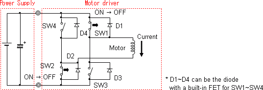
Fig.2.1 The circuit for operating the motor
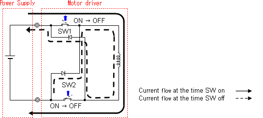
Fig.2.2 The reverse current from the motor to the power supply
The out put voltage of the power supply might be increased and be shut down by the overvoltage protection, for the same reason. Therefore, if the motor, the inductance and so on is used as the load, the diode for protection from the reverse current flow needs to be installed for not increasing the output voltage of the power supply.

Fig.2.3 The circuit for protection from the reverse current flow
Does rated power change when output voltage adjusted?
1. Summary
If the power supply is used in the condition that the output voltage of the power supply is adjusted, the output power and output current must be considered.
2. The output voltage setting
2.1 Output voltage exceeds the rated voltage
Please refer to the formula (1) for the maximum output power. The power supply is not allowed to be operated in the output power that exceeds the maximum output power because the power supply gets broken due to heating of the internal components.
Maximum output power = Rated output voltage x Rated output current-----------(1)
- ex.)The case that the output voltage of the PJA600F-12 is changed to 12.5V
The maximum output current that the power supply is allowed to be operated
= Maximum output power / Output voltage setting
=600W/12.5V
=48A
2.2 Output voltage is less than the rated voltage
Please keep the output current less than the rated current even though the output current calculated by formula (1) is higher than rated current. Over current protection would be activated when output current exceeds 105% of rated current.
- ex.)The case that the output voltage of the PJA600F-12 is changed to 12.5V
Cautions when connecting FG and -V.
1. Connection between FG and -V
Connecting FG terminal and an output -V terminal don't cause any problem in the operation of a power supply. However, if you do so, specifications regarding withstand voltage between secondary side and FG as well as primary and secondary sides will not be satisfied. Doing so also turns insulation between primary and secondary sides into basic insulation and that doesn't meet safety standards.
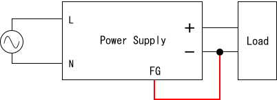
Fig.1 Connecting FG Terminal with -V Terminal
2. Influence of eliminating secondary ground capacitor
If a ground capacitor on the secondary side is eliminated, electrical potential (output voltage) on the secondary side may become unstable. It will also increase output common mode noise. Therefore, please evaluate carefully before eliminating the ground capacitor on the secondary side.
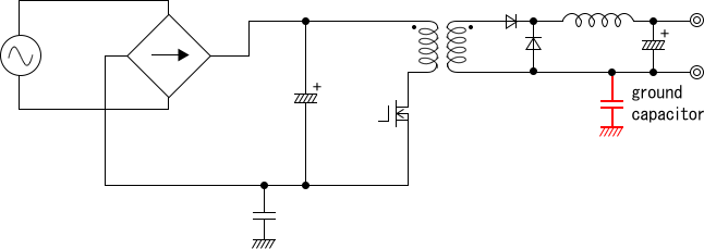
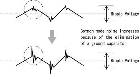
Fig.2 Eliminating a ground Capacitor on the Secondary Side
What is output voltage setting and accuracy?
1. Output voltage setting
Output voltage setting means a range of output voltage set in the factory when product is shipped.
Output voltage is set to rated input voltage at rated load.2. Output voltage accuracy
Output voltage accuracy means total output voltage fluctuation which is sum of line regulation, load regulation and temperature regulation.
Following shows formula of output voltage accuracy.Voltage accuracy ΔV= ± (Line regulation + Load regulation + Temperature regulation) ÷ 2 e.g) Output voltage accuracy of PCA600F-24Voltage accuracy ΔV = ± (Line regulation + Load regulation + Temperature regulation) ÷ 2
= ± (96mV + 150mV + 240mV) ÷ 2
= = ± 243mVHow to calculate external capacitor value from required hold-up time?
1. Requirement of the extension of hold-up time
The demand for the longer hold-up time is increasing in order to keep output voltage during the instantaneous interruption.
Adding a smoothing capacitor enables to extend hold-up time (Th), and adding output capacitor enables to extend fall time(Tf).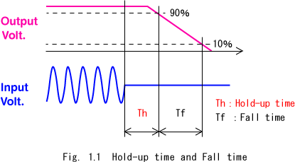
2.Extension method of hold-up time
1) In the case of AC-DC converter
It is necessary to increase the capacitance of smoothing capacitor on primary side to extend hold-up time.
The TU series have design flexibility and hold-up time can be extended by adding a smoothing capacitor externally.
In LFP240F/300F, the external capacitor unit is available as optional parts (available only with -U1Y option).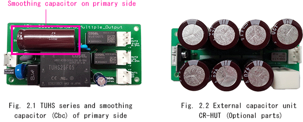
2)In the case of DC-DC converter
It is necessary to add an external capacitor between +Vin and -Vin to extend hold-up time.
3.Calculation formula of required capacitance for hold-up time
External capacitor (Cbc) value can be calculated with following formula.

Calculation example
-Product: TUHS10F05
-Input voltage: 100Vac
-Output power: 4W
-Required hold-up time: 200ms
-Ambient temperature: -20ºC1) Efficiency(η) and minimum input voltage for regulated output voltage(Vh) of TUHS10F05 are listed in test data.
η:Efficiency (by Load Current) of P.4 at test data, at 100Vac, 0.8Aout, Efficiency is 80.6%.
Vh:Minimum Input Voltage for Regulated Output Voltage of P.21 at test data, at 50%out, -20ºC,
Minimum Input Voltage for Regulated Output Voltage is 38Vac.2) Cbc value can be calculated by above formula.

3. EMC
Where is noise sources and pathway in PSU?
1. Souces
Some noise will occur from the switching power supply because it operates by controlling the switching high voltage. Their main sources are shown in Fig.2.1
- Switching transistor ----- (a)
- Output rectifier ----- (b)
- Output transformer ----- (c)
2. Pathways
The noises occurring from power supply are classified into several kinds as shown below based on the pathways. The pathways of noise are shown in Fig.2.1
- Line conduction: Conducted from input terminal of power supply
- Differential-mode noise: Occurring between the AC input lines ----- j
- Common-mode noise: Occurring between the AC input line and FG ----- k
- Output noise: Conducted from output terminals of power supply
- Differential-mode noise: Occurring between output lines ----- l
- Common-mode noise: Occurring between the output line and FG ----- m
- Radiated emission: Radiating from power supply or input/output line directly ----- n
(Radiation noise)
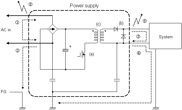
Fig.2.1 The souces and pathways of noise
Noise (Emission/EMI) type and How to reduce?
1. The different types of noise
The noise generated in power supply are divided according to the conduction pathway as shown below.
There are two main types of electrical emissions generated in power supply--conducted emission and radiated emission.
(1) Conducted noise
- Input side (Line conduction)
- Differential-mode noise ----- ①
- Common-mode noise ----- ②
- Output side
- Differential-mode noise ----- ③
- Common-mode noise ----- ④
(2) Radiated noise (Radiated emission) ----- ⑤
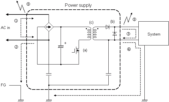
Fig.1.1 The conduction pathways of noise
2. Countermeasures for noise occurring from the power supply
2.1 Countermeasures for conducted noise
(1) Countermeasures for line conduction
A noise filter is built in the power supply in order that a noise occurring from the inside of power supply doesn't return to input side. Please keep the output line and the input line separate when doing wiring, so as to avoid spoiling the effect of noise filter. In addition, to keep the input line away from the effect of radiated noise, please place the input line away from power supply.
Furthermore, to reduce the noise radiated from power supply and to avoid receiving an effect of noise due to long input line, please assemble external noise filter at the AC terminal of the unit case.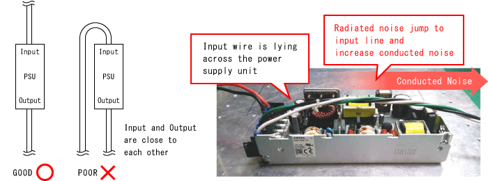
Fig.2.1 The conduction pathway of noise
(2) Countermeasures for output noise
It is important to wire a power supply with thick and short wires. Differential-mode noise and common-mode noise can be reduced by setting a capacitor or a filter on the output line.
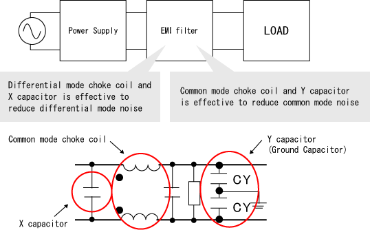
Fig.2.2 Countermeasure for output noise
2.2 Countermeasures for radiated noise (Radiated emission)
A Noise becomes radio waves and radiates to midair, by cables such as the input line, the output line and the signal line extending toward the outside of unit which have antenna effect.
For the above reason, please firstly take countermeasures to avoid conducting a noise to input/output line. If it is not enough, please use some components such as noise filter or data line filter.
It is also effective to use a metal board or a metal film to shut the noise up in the power supply if the unit case is not metal.
Radiated noise from power supply contains high frequency noise and shield effect is depending on installation and environmental condition.
Ideally, power supply and chassis of application shall be connected to same chassis.In case that power supply and chassis are separated, please do grounding the chassis of application via metal plate.
It makes low impedance between power supply and application, and becomes less affected from noise source.- Input side (Line conduction)
Noise (Immunity/EMS) type and How to protect?
1. Types of EMS
The noises which is applied to power supply coming from outside are shown as below.
- Electrostatic discharge immunity
- Impulse noise, Electrical fast transient/burst immunity
- Surge immunity
- Conducted Disturbances, induced by radio-frequency fields
- Radiated, radio-frequency, electromagnetic field immunity
2. Countermeasures for EMS
(1) Countermeasures in power supply
Basically, countermeasures for EMI could be effective for noise immunity as well. Therefore, various countermeasures for EMI play key role for noise immunity.
The following countermeasures are taken in power supply.- Built-in input filter.
- Optimized FG line in design of printed-circuit board and chassis.
- Use noise suppression devices, such as ferrite core, differential-mode choke.
(2) Countermeasures in user's system
EMC directive is generally applied to the end use product. Therefore, the following countermeasures should be taken to the whole system as well as power supply.
- External filter / Surge absorber
Setting a surge absorber or a filter for tolerating impulse noise at AC terminal of the unit will be effective to reduce high-voltage noise.
* When EMI filter is used at input line and surge voltage is applied, there is possibility that input voltage jumps up due to the energy stored in choke coil of EMI filter.
Sufficient evaluation is required to choose suitable EMI filter with actual application. - Wiring of input line / output line
The input line and the output line should be separated to avoid spoiling an effect of noise filter. - Earthing wire
Earth potential is ideally stabilized potential. However, depending on the way of wiring, impedance will be increased and it may cause failure/malfunction of system due to conducted noise.
Earthing wire should be thick and short as possible.
What is EMI filter recommended for DC-DC converter?
Fig.1 shows external noise filter which reduce the line conducted noise for DC-DC converter.
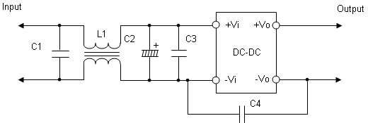
Fig.1 Example of noise filter
Table 1. cable list
No. Parts No. Components Note 1 C1 Ceramic capacitor Low impedance
(recommended value: 4.7uF)2 C2 Electrolytic capacitor Low impedance
(please see instruction manual on catalogue)3 C3 Ceramic capacitor Low impedance
(recommended value: 4.7uF)4 C4 Ceramic capacitor Low impedance
(recommended value: 1000pF)5 L1 Common mode coil High leakage inductance
(recommended: main 14mH, leakage 240uH)The wiring method, the component's location or some other conditions are effect on line conducted noise. Please evaluate under end-use condition before using.
- * Please consider about C4. The permeation noise from input to output will be increased by C4.
4. Protection circuit
What is Inrush current protection?
When input voltage is applied to power supply, inrush current flows to smooth capacitor, then it will cause input switch melting / blown-up.
Therefore, inrush current protection circuit is installed in power supply to prevent it.1. Resistor limit method (Fig.1)
There are 2 methods available. One is adding resistor in an input line, and the other one is using impedance of line filter. However, the power loss is always generated during operation in these methods. Therefore, these methods are used for the low output power unit.
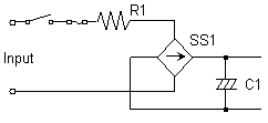
Fig.1 Resistor limit method
2. Thermistor method (Fig.2)
Thermistor is installed in an input line to reduce the inrush current. This method utilizes thermistor characteristic below.
At low temperature: Thermistor has high resistance value.
At high temperature: Thermistor has Low resistance value.[Description]
- (1)Inrush current is suppressed by thermistor (represent high resistance value) when input voltage is applied.
- (2)Since thermistor temperature increases due to input current, the resistance value becomes low. Therefore, the power loss of thermistor is also low.
Note)
If input voltage is re-applied before the power supply gets cool down sufficiently, the inrush current would be higher because thermistor impedance is still low.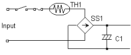
Fig.2 Thermistor method
3. Thyristor:SCR method (Fig.3)
SCR and cement resistor are used in this method.
[Description]
- (1)Inrush current flows through cement resistor (R1) when input voltage is applied (SCR1: OFF).
- (2)SCR1 will be turned-on after some time delay (Resistor power loss will be reduced).
- (3)If C1 has not been charged completely when SCR1 is turned on, the second inrush current will be observed.
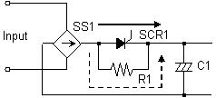

Fig.3 Thyristor method
In DC-DC converters, since almost all of product don't have an input smooth capacitor (C1), inrush current protection circuit is not installed. However, if the input voltage in which rise-up time is rapid is applied, or a mechanical switch is used for power-on/off, please note that the inrush current will be observed for a short time (a few micro-seconds).
4.DC-DC converter
Since DC-DC converter doesn't have large capacitor in input circuit, inrush current protection circuit is not built in. Therefore, when input voltage is rapidly changed or applied by mechanical switch, inrush current would flow at a very short term. In case that external capacitor is used in front of DC-DC converter, inrush current protection circuit in Fig.4 is effective to reduce inrush current.
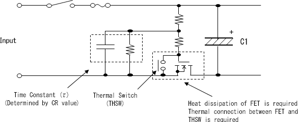
Fig.4 Example of inrush current limiting circuit for DC-DC converter
How to protect DC-DC converter against reverse voltage?
Avoid the reverse polarity input voltage. It will break the power supply. It is possible to protect the unit from the reverse input voltage by assembling the external diode. Please refer to the following.
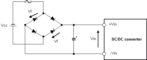
Fig. 1.1 Example of reverse input voltage protection circuit vol.1

Fig. 1.2 Example of reverse input voltage protection circuit vol.2

Fig. 1.3 Example of reverse input voltage protection circuit vol.3
Table 1.1 Feature of reverse input voltage protection circuit Fig.# Operation during applied reverse polarity voltage Advantage Disadvantage Cost 1.1 Normal operation * Normal output
* No component required for reocovery* Not detectable reverse connection
* Diode power loss constantlyHigh 1.2 No output * Detectable of reverse connection
* No component required for reocovery* No output after reverse connection
* Diode power Loss constantlyLow 1.3 No output
Fuse open* Detectable reverse connection
* No diode power loss* Fuse replacement required for recovery
* Overcurrent for an instantMedium
5. Attached function
How to use remote sensing in series/parallel connection?
A remote sensing function can be used even if the power supplies are connected in series or parallel. Please refer to the following for wiring of the remote sensing. Also, please install capacitors between the sensing line (+S and -S) and the output line (+V and -V) if output voltage gets unstable.
1. Series operation
The wiring of the remote sensing depends on the kind of the load when the power supplies are used in the series operation.
- Series operation with no center point (used as single output)
Using only remote sensing terminal connecting to the load. Please refer to Fig. 1.1. - Series operation with center point (used as dual output)
Connecting the remote sensing terminals to each loads that connect to each power supplies. Please refer to Fig. 1.2.
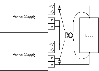
Fig. 1.1 Series operation with no center point
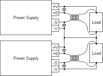
Fig.1.2 Series operation with center point
2. Parallel operation
The power supply must have the parallel operation function in the case of the parallel operation. Only sensing terminal of the master unit connects to the load. Please refer to Fig. 2.1.
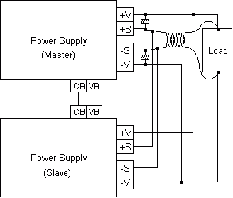
Fig. 2.1 Parallel operation
- Series operation with no center point (used as single output)
What's the difference between parallel / redundancy operation?
1. Parallel operation
"Parallel operation" is the way increasing the output power by connecting in the parallel to supplement the lack of the output power. If the power supply is operated in the parallel, to use the power supply that has the parallel operation function ( the current balance function) is general. However, if the option "-P" is used or put the diode as a simple method the power supply that does not have the parallel operation function might be able to be used in the parallel operation.
2. Redundancy operation
2.1 Redundancy operation
"Redundancy operation" is also called " Backup operation". It is same as "Parallel operation" about the part connecting in the parallel, but its purpose is not to increase the output power. It is the way of connecting the reserve of the power supply to not stop the system even if the power supply become broken.
If the "Redundancy operation" is done, it is general to connect the reserve of the power supply in which rated current is same as the main power supply. Also, if the power supply is used in the parallel operation, same number of power supplies are needed. Please refer to Fig. 2.1.2.2 N+1 Parallel Redundancy operation
In the general redundancy operation, if the system that has some power supplies connected in the parallel is composed, same number of power supplies as them are needed. Please refer to Fig. 2.2.
"N+1 parallel redundancy operation" is the way that several power supplies share the power needed to the system, and one power supply for redundancy is connected to the system.
This way can constitute the system that is cheaper than normal system when the power of the system is big, because of the following.
* The redundancy operation is constituted by increasing the quantity of the power supply and sharing the power.
* One of the power supply is used as the spare power supply because of not stopping the system even if one of the power supply becomes broken. Therefore, the spare power supply is enough even if its power is small.
And, if the power supply that has the function for the parallel operation is used, the output voltage of the power supply that has the function for the parallel operation is dropped when one of the power supply is broken. The function for the parallel operation tries to keep the output current 0A,
because the output current of the broken power supply is 0A.
Therefore, the power supply in which output voltage is not decreased even if another power supply is broken needs to be used, when the power supply is used for redundancy operation.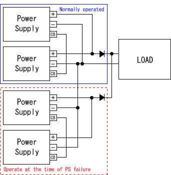
Fig.2.1 Example of normal redundancy operation
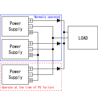
Fig.2.2 Example of N+1 parallel redundancy operation
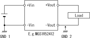
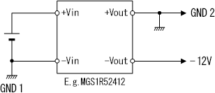
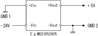
Show DC-DC converter application circuit
1.Input Voltage for DC/DC converter
- (1) When using AC/DC power supply
- (2) When using AC voltage source
- (3) When using a Battery-operated Device
2.Using DC/DC converter
- (1) When a Floating Mechanism is Required for Output Circuit
- (2) To draw a Reverse Polarity Output
- (3) To provide a negative voltage to -Vin by using +Vin side of the converter as GND potential (0V)
- (4) To draw the Sum of Input Voltage and Plus Output Voltage
3.Using a Dual Output Type
1. Input Voltage for DC/DC converter
(1) When using AC/DC power supply

(2) When using AC voltage source
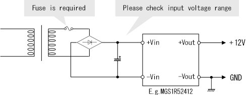
(3) When using a Battery-operated Device
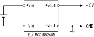
2. Using DC/DC converter
(1) When a Floating Mechanism is Required for Output Circuit
(2) To draw a Reverse Polarity Output
(3) To provide a negative voltage to -Vin by using +Vin side of the converter as GND potential (0V)
(4) To draw the Sum of Input Voltage and Plus Output Voltage
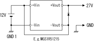
- Output current shall be less than rated current.
- Total Output voltage regulation is sum of input voltage regulation and output voltage regulation.
- When output voltage is shorted, huge current would flow depending on input voltage source.
3. Using Dual Output Type
(1) Using dual output type
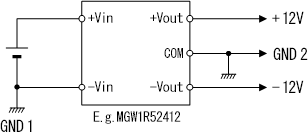
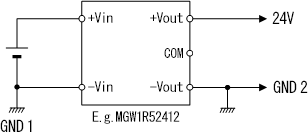
(2) Using +/-12V as 24V output
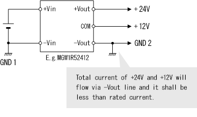
(3) Using +/-12V as multi output +12V and 24V
(4) Using as 48V output
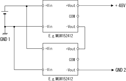
What "Open collector" means?
Some products have alarm function by using transistor output type.
Most common type is "Open collector" output and it can be used to detect operation of power supply.
Open collector behaves like switch that is either connected to signal ground or disconnected.
External voltage source is required to pull-up the signal voltage.
Current limiting resistor is required not to exceed maximum collector current which is shown in instruction manual.
Fig.1 Internal circuit of alarm function
Response time to become "High", depends on the product and condition.
Isolation of alarm signal depends on the product and please refer to instruction manual for detail.
Some products have AUX and AUX can be used as external voltage source.
Output current of AUX shall be within the rated current of AUX.How to use Remote Control Function with -R option?
(Enclosed and Open frame type Power Supply)R option is the function to control remote on/off by applying DC voltage from external voltage source to remote on/off pin.
Optional harness is available and line-up is shown in catalog of optional parts.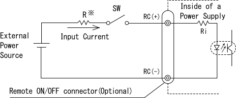
Fig1. Example of using a remote ON/OFF circuit
When 4.5-12.5V is applied between RC and RCG pin, power supply turns on.
Below table shows specification of remote on/off condition.Table1. Condition of remote ON/OFF Internal resistor is different depends on the product Voltage between RC and RCG [V] Current [mA] Output ON Output OFF 4.5~12.5 0~0.5 (20max) When external voltage is 4.5-12.5V, additional external resistor is not needed.
When using more than 12.5V to remote on/off, current limiting resistor shall be added externally.
Following formula shows how to calculate value of current limiting resistor.
Please do not apply reverse voltage, since it cause failure of internal circuit.
Generally, remote on/off circuit is isolated from input, output and FG.
For detail, please refer to instruction manual.Cautions in Series Operation
1. Cautions in Series Operation
There are some concerns for internal component rating or isolation distance because high voltage would be applied between the output and FG when the power supply is connected in series. Please consider following points when series operation is required.
(1) Most of our products are designed to be certified as "SELV (Safety Extra Low Voltage)" on the output, therefore the operating output voltage should designed to 60VDC (or 42.4Vpeak). When the power supply connects in series and total output voltage exceeds 60VDC, safety approval for the product is invalid.
(2) Do not connect the output circuit to FG in common.
If the output is connected to FG, high voltage would be applied to the secondary grounding capacitor or functional circuit connector on the top side of the unit connected in series. If the applied voltage exceeds the rating of the grounding capacitor or functional circuit connector, the electrical stress would be applied to the part. Regarding internal components rating, please contact us.(3) Even though the secondary circuit is floating, high voltage would be applied between output and FG. Therefore, the foreign objects would cause short circuit or failure. Please make sure the measures against the failure caused by external objects.
(4) Please pay attention to the treatment of high voltage such as the isolation between FG and output circuit even if the power supply is installed to the equipment.
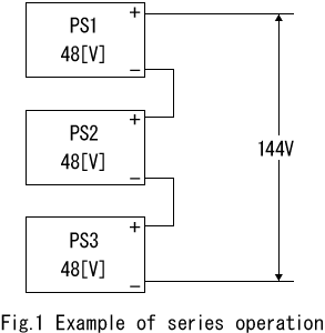
Cautions in Series Operation of Power Supply
with Synchronous Rectification Circuit1. Synchronous Rectification
Synchronous Rectification is one of the circuit topology to improve efficiency and generally its topology is used for rectification circuit at secondary side.
MOSFETs is used for rectification instead of diode.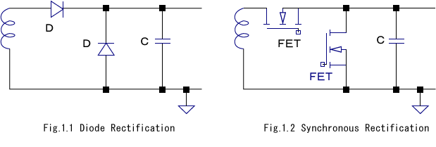
2. Behavior in series operation when one side power supply shut down
When one side of power supply shut down in series operation, synchronous rectification MOSFET turns off. Operating power supply continues to generate the output current and output current flows via body-diode of MOSFET in the power supply which is shut down.
The forwarding voltage (Vf) of body-diode in MOSFET is approx. 0.7-1.3V and power loss of MOSFET is higher than normal operation.
To prevent this issue, schottky barrier diode which has low Vf characteristics is recommended to put between output voltage.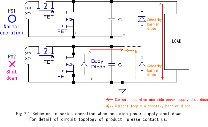
For detail of circuit topology of product, please contact us.
6. Others
What is measurement item in TEST DATA?
TEST DATA is available to download on website. (TEST DATA is measured by 1 sample.)
Following Table shows explanation of measurement items.Table1. Explanation of Measurement Item in TEST DATA No. Measurement Items Explanation 1 Input Current
(by Input Voltage)Input current depends on input voltage(Input current increases when power supply activates.) 2 Input Current
(by Load Current)Input current depends on load current 3 Input Power
(by Load Current)Input power depends on load current 4 Efficiency
(by Input Voltage)Efficiency depends on input voltage 5 Efficiency
(by Load Current)Efficiency depends on load current 6 Power Factor
(by Input Voltage)Power factor depends on input voltage 7 Power Factor
(by Load Current)Power factor depends on load current 8 Inrush Current Surge input current when power supply start up.(Duration is 5ms max) 9 Leakage Current Leakage current flow to the earth from power supply 10 Line Regulation Output voltage fluctuation when input voltage changes slowly 11 Load Regulation Output voltage fluctuation when load current changes slowly 12 Dynamic Load Response Output voltage waveform when output current changes dynamically 13 Ripple Voltage
(by Load Current)Ripple voltage depends on output current 14 Ripple-Noise Ripple noise depends on output current 15 Ripple Voltage
(by Ambient Temperature)Ripple voltage depends on temperature 16 Ambient Temperature Drift Output voltage fluctuation depends on temperature 17 Output Voltage Accuracy Fluctuation ratio of output voltage depends on input voltage, output current and temperature 18 Time Lapse Drift Output voltage drift from 30 minutes to 8 hours 19 Rise and Fall Time Output voltage rise time from 10% to 90% of rated voltage, and fall time from 90% to 10% of rated voltage 20 Hold-Up Time Output voltage holding time after input voltage shut down 21 Instantaneous Interruption Compensation Input voltage interruption time which output voltage can be kept at rated voltage 22 Minimum Input Voltage for Regulated Output Voltage Input voltage when output voltage drop less than 95% of rated voltage or ripple voltage exceed the specification 23 Overcurrent Protection Load impedance changes from infinity to 0ohm, then measure the load current when output voltage drops to 95% of rated voltage. 24 Overvoltage Protection Over voltage protection activating voltage 25 Figure of Testing Circuitry Circuit diagram which is used for measurement *Measurement items are different depends on the product.
How to calculate calorific value?
The calorific value in power supply depends on power consumption as well as other electronic equipment. The calorific value is shown as following.
1 [Ws] = 1 [J]
It can be expressed in "cal" as follows as well.
1 [Ws] = 0.239 [cal]
For example, the power consumption of a power supply shown in the following spec can be calculated as follows.
[Spec]
- Output voltage: 5V
- Output current: 10A
- Efficiency: 80%
- Operating time: 1hr
Internal Power Loss: P
= Active Power - Output Power
= (Output Voltage x Output Current / Efficiency)
- (Output Voltage x Output Current)
= (5 x 10 / 0.8) - (5 x 10)
= 12.5 [W]Calorific Value: J
= Internal Power Loss [W] x Time [s]
= 12.5 x 3,600
= 45,000 [J]
= 45,000 x 0.239
= 10,755 [cal]What does the content indicated on name plate mean?
1. Content indicated on the name plate
The name plate on the power supply indicates the rated output voltage range which is approved by safety agency like UL, CSA or TUV.
For example, with respect to UL60950-1, the following contents are required.- Rated voltage or the rated voltage range
- Rated frequency or the rated frequency range (excluding DC converter)
- Rated current
- Manufacturer name, trademark or other distinguishable marks
- Model name or type classification
2. Difference between input voltage range indicated on the name plate and spec.
The input voltage range presented in the specifications shows the range in which the power supply can be used and its electrical characteristics will be guaranteed.
On the other hand, the name plate on the power supply indicates the rated output voltage range which is approved by safety agency but the power supply can be used at the input voltage range presented in the specifications.How to read lot number?
1. Description of Lot Number
<Example 1>

<Example 2>

- ①Assembled Country
Blank Japan L China - ②Assembled Year
Japan Product <Example 1>:Last Digit of the Christian Era
China Product <Example 2>:Last Two Digit of the Christian Era- ③Assembled Week
Week number from 1st (1st Jan.) to 52nd (31st Dec.)
- ④Management Number for Production Line
0001-9999
- ⑤Factory Code
- ⑥RoHS Compatibility
R RoHS Comply e Assembled in lead free soldering process Blank No RoHS Comply What's QR code meaning?
(Enclosed and Open frame type Power Supply)1. Contents of QR code
< Example of QR Code >

< Example of text >
COSEL 123456 JPN 18 01 1234 T 0001
① ② ③ ④ ⑤ ⑥ ⑦ ⑧- ①Company Name
- ②Product Identification Code
6 Digit Code depends on the Product series
- ③Assembled Country
JPN Japan CHN China - ④Assembled Year
Last Two Digit of the Christian Era
- ⑤Assembled Week
Week number from 1st (1st Jan.) to 52nd (31st Dec.)
- ⑥Management Number for Production Line
0001~9999
- ⑦Factory Code (Blank in some products)
- ⑧Serial Number in Same Lot No.
0001~9999
* On-board type power supply and EMI filter have different text in QR code.
QR code is for production management in COSEL.
Contents of QR code is subject to change without any notice.Ordering information for Semi-standard.
1. What is Semi-Standard?
Cosel provides various optional functions for standard power supply to accommodate user needs. Additional feature or function is available by adding Optional Suffix Code following the model name.
<Example>

2. Optional Suffix Code Configuration with more than 2 options
(1)Enclosed type
<Example 1>

Suffix N (Cover option) shall be added at the end.
<Example 2>

In case of no Suffix N, Suffix code shall be sequenced alphabetically.
(2)Open frame type
<Example 1>

Suffix S(Chassis) and Suffix N(Cover) shall be sequenced at the beginning of optional code.
<Example 2>

In case of no Suffix S and N, Suffix code shall be sequenced alphabetically.
When combined multiple suffix code, customized suffix code might be required depends on product.
The combination of Suffix Code might be unavailable depends on the functions.
For detail, please feel free to contact us.Withstand Voltage and Insulation Resistance Test Instructions
Please take the following instructions into consideration in running a withstand voltage test and an insulation resistance test as an incoming inspection.
1. Voltage applying method
When running a withstand voltage test, please apply voltage gradually from 0V, or by using zero-crossing switch in order not to cause a surge voltage.
Same as the case of applying voltage, when shutting off voltage, please decrease the applied voltage gradually or by using zero-crossing switch.2. Applied voltage
Depending on the kind of withstand voltage tester, applied voltage may be deformed or high voltage may occur in the electric circuit.
Therefore, please keep observation on the applied voltage wave pattern during the test.3. Residual voltage
After an insulation resistance test, discharge the voltage remaining inside the Y-capacitor by resistance.
*Reference: Test circuit in COSEL
In withstand voltage isolation resistance test, L and N are shorted and +Vout and -Vout are shorted as shown in Fig.3.1 - Fig.3.3.
This test method is based on JEITA RC-9131.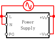
Fig.3.1 Between Input and Output
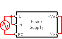
Fig.3.2 Between Input and FG
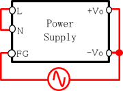
Fig.3.3 Between Output and FG
Why does LED light during Withstand Voltage Test?
1. Generation mechanism
When hi-pod voltage is applied between input and FG, electric charges pass through ground capacitor C2 and C3, and electrifies C1. And if the voltage charged on C1 reaches to the start-up voltage of switching power supply, switching circuit (TR1,OT) will operate and then output voltage will be generated. However, there are only a few electric charges charged on C1, so switching circuit will shut off immediately.
The above process will be repeated since voltage is applied, and pulse-shape voltage will occur on the output. As long as the circuit is operated under control, there is no probability that output voltage will rise and exceed the rated voltage. In addition, there is no influence for the reliability of power supply because there is no abnormal voltage occurring on the internal components of power supply.
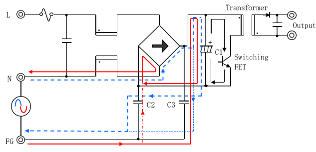
Fig.1 Circuit diagram of the inside of a power supply
2. Safety of output load equipment
We consider there is no impact on the load equipment because the output voltage will not exceed the rated voltage. However, in case if some countermeasures are required due to the characteristics of the equipment, make a short circuit between the output terminals during the test.
What is Difference between PBA series and PJA/PLA series?
PBA/PJA/PLA series are "Unit Type" power supply. The line-up is shown in Table 1.
PJA/PLA series is lower price model of PBA series and specification is different partially. Table 2 through 5 shows the specification comparison and the suitable product shall be selected for the requirement.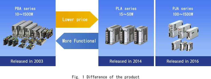
Table 1 Output power Rated output power [W] 10 15 30 50 75 100 150 300 600 1000 1500 PBA ● ● ● ● ● ● ● ● ● ● ● PLA,PJA PLA - ● ● ● - - - - - - - PJA - - - - - ● ● ● ● ● ● Table 2 Comparison up to 75W models No. Subject Specifications PBA10F/15F/30F
/50F/75FPLA15F/30F/50F Notes 1 Electrical characteristics Input voltage AC85-264V AC85-264V
(Required derating at less than AC115V input)2 Efficiency [%] 10W 77typ - Reference value of DC24V output mode
AC200Vin,Io=100%(PBA)
AC230Vin,Io=100%(PLA)3 15W 78typ 80typ 4 30W 81typ 83.5typ 5 50W 84typ 84typ 6 75W 85typ - 7 Operating temperature -10℃-71℃ -20℃-70℃ PLA series require ambient temperature derating at -10ºC - -20ºC. 8 Structure Size 10W 31×78×68mm - Exclude terminal block and screw 9 15W 31×78×85mm 38×80×73mm 10 30W 31×78×103mm 38×80×88mm 11 50W 31×82×120mm 38×80×99mm 12 75W 32×82×135mm - 13 Case & Cover Standard model has Chassis only (-N option : with cover) With Chassis and Cover for standard model 14 Cooling method Convection Convection Hatched areas have advantage against the competitive model.
For more details, please see specification and instruction manual on our website.Table 3 Comparison for 100W/150W models No. Subject Specifications PBA100F/150F PJA100F/150F Notes 1 Electrical characteristics Input voltage AC85-264V AC85-264V
(Required derating at less than AC115V input)2 Efficiency [%] 100W 86typ 88typ Reference value of DC24V output model
AC200Vin,Io=100%(PBA)
AC230Vin,Io=100%(PJA)3 150W 88typ 90typ 4 Operating temperature -10℃-71℃ -20℃-70℃ PJA series require ambient temperature derating at -10ºC - -20ºC. 5 Structure Size 100W 32×93×147mm 41×97×109mm Exclude terminal block and screw 6 150W 34×93×168mm 41×97×129mm 7 Case & Cover Standard model has Chassis only (-N option : with cover) With Chassis and Cover for standard model 8 Cooling method Convection Convection 9 Functions Reduce power consumption × ○
(Power consumption at no load :1.5W typ)Ripple/ripple noise specification for PJA series change at Io=0-30% in order to reduce power consumption. Hatched areas have advantage against the competitive model.
For more details, please see specification and instruction manual on our website.Table 4 Comparison for 300W/600W models No. Subject Specifications PBA300F/600F PJA300F/600F Notes 1 Electrical characteristics Input voltage AC85-264V AC85-264V
(Required derating at less than AC115V input)2 Efficiency [%] 300W 82typ 86typ Reference value of DC24V output model
AC200Vin,Io=100%(PBA)
AC230Vin,Io=100%(PJA)3 600W 84typ 88typ 4 Peak output current ○
Available for DC24V output, with condition at AC200V input× 5 Operating temperature -20℃-71℃ -20℃-70℃ 6 Structure Size 300W 102×42×170mm 102×41×190mm Exclude terminal block and screw 7 600W 120×61×190mm 120×61×215mm 8 Cooling method Forced air (Intake air) Forced air (Exhaust air) 9 Functions Adjustable near 0V ○ × Refer to catalog and instruction manual 10 Output voltage adjustment by external signal ○ × 11 AUX ○ × 12 Remote control ○ ×
Possible by option -R (External voltage source is required)13 Remote sensing 300W ○ × 14 600W ○ ×
Possible by option -W15 Alarm 300W ○ × 16 600W ○ ×
Possible by option -W17 Parallel operation 300W ○ × 18 600W ○ ×
Possible by option -WHatched areas have advantage against the competitive model.
For more details, please see specification and instruction manual on our website.Table 5 Comparison for 1000W/1500W models No. Subject Specifications PBA1000F/1500F PJA1000F/1500F Notes 1 Electrical characteristics Input voltage AC85-264V
(Required deraing at less than AC90V input for PBA1500F)AC85-264V
(Required derating at less than AC115V input)2 Efficiency [%] 1000W 86typ 88typ Reference value of DC24V output model
AC200Vin,Io=100%(PBA)
AC230Vin,Io=100%(PJA)3 1500W 87typ 88typ 4 Peak output current ○
PBA1000F:Available for DC24V output, with condition at AC200V input
PBA1500F:Available for DC24V/36V output, with condition at AC200V input× 5 Operating temperature -20℃-71℃ -20℃-70℃ 6 Structure Size 1000W 150×61×240mm 150×61×240mm Exclude terminal block and screw 7 1500W 178×61×268mm 178×61×268mm 8 Cooling method Forced air
(Intake air)Forced air
(Exhaust air)9 Functions Adjustable near 0V ○ × Refer to catalog and instruction manual 10 Output voltage adjustment by external signal ○ × 11 AUX ○ × 12 Remote control ○ ×
Possible by option -R (External voltage source is required)13 Remote sensing ○ ×
Possible by option -W14 Alarm ○ ×
Possible by option -W15 Parallel operation ○ ×
Possible by option -WHatched areas have advantage against the competitive model.
For more details, please see specification and instruction manual on our website.What is Difference between KH and KL series?
KH and KL series is the AC/DC power supply which specify DIN rail mounting.
KL series is lower price model of KH series and the specification is different partially.
Table 1 shows the specification comparison and the suitable product shall be selected for the requirement.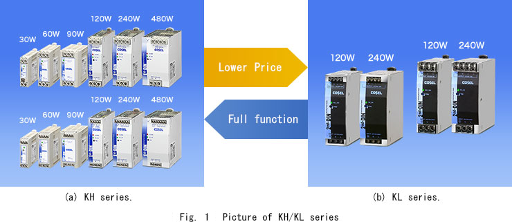
Table.1 Specification Comparison # Index KHEA/KHNA
120F,240FKLEA/KLNA
120F,240FNote 1 Output Voltage DC24V DC24V 2 Electrical
characteristicsInput voltage *1 AC85-264V
DC88-370V*1
*External DC fuse is NOT requiredAC85-264V
DC120-370V*1
*External DC fuse is required3 Efficiency
(Vin=230V)120F 92.0% 88.0% 4 240F 94.0% 90.0% 5 Output voltage adjustment range -7%-19%
(22.5-28.5)±10%
(21.6-26.4)6 Peak capability ○
150% peak available within 5 sec×
N/A7 Operating temperature *1 -25℃-70℃
-40℃ start up available-20℃-70℃ 8 Temperature derating
(Vin=230V)120F 60℃,100% 55℃,100% 9 240F 60℃,100% 50℃,100% 10 Function DC OK/ALARM DC_OK:Green LED
ALRAM:Red LED
DC_OK:Relay outputDC_OK:Green LED 11 Remote control ○
Built-in×
N/A12 Structure Dimension 120F 37×124×117mm 38×124×117mm 13 240F 50×124×117mm 50×124×117mm 14 Screw hold terminal block
(KHNA,KLNA)○
Built-in×
N/A15 Color White Black 16 Safety Standard AC input UL60950-1,C-UL,EN60950-1,UL508
ANSI/ISA12.12.01,ATEX
(Explosion Protection)
GL
(Marine standard)UL60950-1,C-UL,EN60950-1
(Information Technology Equipment)
UL508
(Industrial Control Equipment)17 DC input UL60950-1,EN60950-1
(Information Technology Equipment)N/A *1 Temperature derating is required (Detail is shown in the instruction manual)
Hatched areas have advantage against the competitive model.
For more details, please see specification and instruction manual on our website.How is the temperature measured?
1. Overview
Power supply is the heat generating part, however it is installed frequently in a narrow space due to the demand of small product. In order to make sure the operating condition, temperature measurement of power supply becomes more important.
However, we have experience that the temperature measurement haven't done correctly due to incorrect measurement.
Therefore, we introduce our temperature measuring methods.2. Temperature measuring method
Table 2.1 shows the Advantage/Disadvantage by temperature measuring method. Cosel usually use thermocouples.
Table 2.1 Advantage/Disadvantage of temperature measurement methods Method Advantage Disadvantage 1 Thermocouples ・Wide measurement range ・Dissipated the heat by the thermocouples ・No extra space is required. ・Low price ・Due to above, it takes time to measure temperature. ・Possible to measure the inside of the object Possible to measure the air temperature. ・Necessary to connect the measurement reference point properly to the object 2 Infrared radiation thermometer ・Measure without contact ・Impossible to measure the inside of the object. Impossible to measure the air temperature. ・Measurement result changes by the emissivity of the object. ・Influenced by the environment. 3 Thermography ・Measure without contact ・Impossible to measure the inside of the object.
Impossible to measure the air temperature.・Measurement result changes by the emissivity of the object. ・Measure whole range of the view ・Influenced by the environment. ・Expensive 3. How to choose the type of thermocouples?
There are many types of thermocouples by material or thickness. It is necessary to
choose thin size one to avoid the heat dissipation from the target devices.
We uses following thermocouples which the thermal conductivity is relatively small
and the wire is thin.
1) Type:Type K (Base metal +:Ni/Cr, -:Ni alloy)
2) Thickness:Φ0.14. How to hold the edge of thermocouples?
The reference contact point must be fixed to the target device to get proper
measurement result.
The fixing methods would be adhesive, resin tape or metal tape etc. We recommend
to use adhesive in the point of view of adhesion at high temperature condition.Operation tutorial of Voltage doubler circuit
As for the power supply which the voltage doubler rectifier is installed in, input voltage is rectified by voltage doubler circuit when the change-over terminal of AC100/200V is set at AC100V. On the contrary, when the changeover terminal is set at AC200V, input voltage is rectified full wave rectifier circuit.
Below shows operation tutorial of voltage doubler rectifier circuit.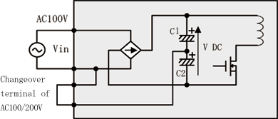
Fig.1 Voltage doubler rectifier circuit
The voltage doubler rectifier circuit as shown in Fig.1 and circuit loop is different between positive voltage and negative voltage.
When input voltage is positive, circuit as shown in Fig.2 will operate and charge C1. On the contrary, when input voltage is negative, circuit as shown in Fig.3 will operate and charge C2.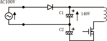
Fig.2 Circuit loop when input voltage is positive
Therefore, V-DC, voltage of C1 + C2, will always fix at DC280V in either case of AC100V or AC200V, and the voltage inside of the power supply will be retained at a constant level.

Fig.3 Circuit loop when input voltage is negative
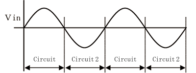
Fig.4 Timing of circuit changeover
7. Component Choice
How to choose External Fuse?
1. Selection method of external fuse
(1) In Case of Fuse Equipped Type
It is not necessary to install a fuse outside of the power supply. However, in case that the output power of usage condition is too small against rated current etc., choose appropriate fuse according to Clause 2.
(2) In Case of Non Fuse Equipped Type
It is mandatory to install a fuse outside of the power supply. Please see instruction manual of each product to check the necessity of external fuse. Applications manual would be available for selection of external fuse (Except a part of products).
2. How to select external fuse?
Here is the point to select external fuse.
< Selection method of external fuse >
(1) Rated voltage : Check the maximum input voltage, and choose higher rating fuse.
(2) Rated current : Choose approx. 1.5 ~ 2.0 times from continuous input current.
(3) Inrush current* : Calculate Joule heat (I^2t) of inrush current.
Time-Lag type (Slo-Blo) should be chosen.
(4) Abnormal condition : Evaluate that the fuse blown out safely.
(5) Safety approval : Choose appropriate fuse for your equipment requirement.* Inrush current term would be approx. 5ms (At 90deg/270deg turn on).
In case of DC-DC converter, the capacitance of external capacitor which is used for stable operation would be higher than internal capacitor. Inrush current would be larger by external capacitance. And there may be influence of line impedance as well, so please evaluate before use.3. Troubleshooting fuse installation
The causes of fuse blowing are almost classified into 3 types. According to the different types of causes, troubleshooting methods are also different. Please refer to table 3 .
Table 3 The causes of fuse blowing and troubleshooting methods No. Trouble Cause Troubleshooting 1 Fuse blowing Internal components broke down by short circuit. Contact us for repair. Because only changing the fuse can not recover the power supply. 2 Current capacity is not large enough. Confirm whether the usage condition against derating (current, temperature) is appropriate or not. 3 Surge resistance is not enough. Confirm whether the inrush current I²t is within the range of fuse resistance. 4. Blown out of built-in fuse
In case of internal fuse blown out, internal components not only fuse but also others shall be broken down for some certain reasons with most cases. So we recommend to ask purchased distributor for repair/analysis.
How to choose Circuit Breaker?
Please keep the following in mind when choosing a circuit breaker to protect the input circuit of switching power supply.
1. Number of Poles
in case of Single-phase electric power
There are AC(L) and AC(N) power line, and AC(N) is the earth electric potential.
If AC(L) and AC(N) can be distinctly known, a single-pole trip breaker is applicable to shut off AC(L) power line. But if AC(L) and AC(N) can't be known clearly, you have to choose a two-pole trip breaker to shut off both of them.In case of Triple-phase electric power
A three-pole trip breaker is necessary to shut off the whole phases.
2. Trip characteristics and rating
Generally, the input circuit of switching power supply is capacitor input type, therefore when power is turned on, a strong surge current, called inrush current, will occur instantaneously in the circuit. Furthermore, inrush current flows through circuit only in several milli-seconds [mS] but it becomes 10 times greater than normal input current. Circuit breaker may be shut off by the inrush current depending on its characteristics. Therefore, circuit breaker should be chosen not to be tripped by the short term inrush current. Generally, it is called "Slow-blow" type breaker.
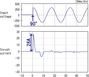
Fig.1 Example of inrush current
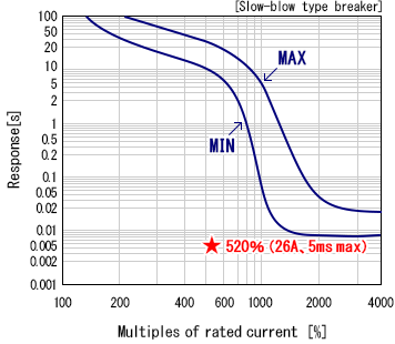
Fig.2 Example of trip characteristics of breaker at 5A
The area encircled by the two curves is the operating range of circuit breaker. Suppose the time of inrush current is 2mS, according to the above graphs, it is out of the operating range of circuit breaker.
Considering the input characteristics of switching power supply, when input voltage phase is 90˚ or 270˚, a peak inrush current will occur and flow through the circuit, however, it will return to 0A in 5mS maximum.
Based on the value of inrush current listed in our catalogue, a breaker which will not operate within 5ms should be chosen. Furthermore, the values of inrush current are measured only when input voltage is set at rated input voltage mostly 100VAC and 200VAC. If you want to use a power supply with higher input voltage than rated input voltage, figure out the multiple of input voltage (100V/200V) and multiply it by the inrush current value listed in our catalogue. (Ex. If [input voltage = 220V], [multiple = 220/200 = 1.1]).
Besides the above considerations, it is also necessary to take the operating temperature into consideration to choose a breaker which will not trip even though a power supply is being used at its maximum operating range.
And finally please pay more attention to the fuse of power supply, because circuit breaker may not operate when power supply has broken down due to fuse blowing.
How to choose wiring cable?
1. The reason why we should pay attention for wiring.
Caution should be exercised in the cable which is used for wiring (input/output line) of the power supply. There is a very low resistance in the electric cable and it causes a problem often. If the current flows through the cable, the resistance causes voltage drops and electric energy is transformed into heat, which raises the temperature of the cable.
For the above reasons, please wire a power supply with short and thick cables.2. The required thickness of cable depends on a current value (reference value).
Table 2.1 cable list No. AWG No. Cross-section Area
[mm2]Line voltage drop per 1A
[mV/m]Max current (Ta=40℃)
UL1015 (600V 105℃)
[A]1 30 0.051 358 - 2 28 0.081 222 - 3 26 0.129 140 5.8 4 24 0.205 88.9 7.6 5 22 0.326 57.5 10.0 6 20 0.517 37.6 13.1 7 18 0.823 22.8 17.2 8 16 1.309 14.9 22.8 9 14 2.081 9.5 30.4 10 12 3.309 6.0 40.6 11 10 5.262 3.8 55.3 * According to the data provided by cable supplier
3. Notes
- It is not good for heat dissipation if bundling up the cables.
Please keep 80% derating of rated current when bundling up 5 or more cables. - The cable has inductance ingredients besides resistance ingredients.
Therefore, please wire a power supply with short and thick cables. - The voltage drops at remote sensing cable should be 0.3V or less
(if using remote sensing function).
- It is not good for heat dissipation if bundling up the cables.
How much is the tightening torque?
Regarding the tightening torque used for terminal block screws, the recommended torque value is shown below.
Evaluation shall be required with your end equipment.1. For Terminal Block
Table 1. Recommended tightening torque value for Terminal Block No. Screw diameter Recommended Torque No. [N·m](sl unit) [kgf](Gravitational system of unit) 1 M3 0.36 - 0.49 3.7 - 5.0 2 M3.5 0.64 - 0.8 6.5 - 8.8 3 M4 1.0 - 1.2 9.6 - 12.8 4 M5 1.9 - 2.4 19.0 - 25.0 5 M6 3.3 - 4.3 33.5 - 44.0 6 M8 8.1 - 10.7 82.0 - 110.0 2. For Mounting hole (Aluminum chassis)
Table2. Recommended tightening torque value for Mounting hole (Aluminum chassis) No. Screw diameter Recommended T or que No. [N·m](sl unit) [kgf](Gravitational system of unit) 1 M3 0.36 - 0.49 3.7 - 5.0 2 M3.5 0.64 - 0.8 6.5 - 8.8 3 M4 1.0 - 1.2 9.6 - 12.8 4 M5 1.9 - 2.4 19.0 - 25.0 5 M6 3.3 - 4.3 33.5 - 44.0 6 M8 8.1 - 10.7 82.0 - 110.0 3. For Mounting hole (Steel plate)
Table3. Recommended tightening torque value for Mounting hole (Steel Plate Chassis) No. Screw diameter Recommended T or que No. [N·m](sl unit) [kgf](Gravitational system of unit) 1 M3 0.46 - 0.6 4.7 - 6.3 2 M3.5 0.79 - 1.08 8.1 - 11.0 3 M4 1.2 - 1.5 12.0 - 16.0 4 M5 2.4 - 3.0 24.0 - 31.0 5 M6 4.2 - 5.4 42.0 - 56.0 6 M8 10.1 - 13.4 103.0 - 137.0 What is Number of Possible Installation Metric Ring Terminals?
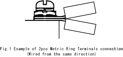
When selecting the thickness of Metric Ring Terminals for connecting to the terminal block of our products, please consider the effective screw part, the insulation distance between the terminals etc. In case the thickness of Metric Ring Terminals is 0.8 ~ 1.0mm, it is possible to use 2pcs of Metric Ring Terminals at the same time for our unit type power supplies or EMI filters.
And please consider the thickness of electric wire in terms of allowable current and voltage drop.
There is a concern of connectivity between two Metric Ring Terminals. There is a possibility that the connection is not constructed properly due to the tilt of terminals caused by the tightening method. We don't recommend to use it in this condition because there is a risk of heating due to the contact resistance. Please make sure that the terminals are installed without any gap and tilt.
We appreciate if you evaluate the actual thickness of Metric Ring Terminals and installation conditions.
8. Reliability
What is expected life of Electrolytic capacitor?
1. Expected Lifetime of Power Supplies
Aluminum electrolytic capacitor is the shortest life parts in power supplies. Other parts, like resin, have also their life, but they are 20 - 30 or over years. So the life on electric devices generally are not problems.
Aluminum electrolytic capacitor is the most important parts in terms of reliabilty, and expected lifetime of power supplies can be estimated by calculating the estimation of expected lifetime of aluminum electrolytic capacitor.
Expected lifetime of aluminum electrolytic capacitor is determined by amount of excess electorlyte, speed of electrolyte evaporating through sealed rubber and temperature that determines the evaporating speed.
The relationship between ambient temperature and capacitor life has been confirmed to follow ARRHENIUS' equation:Expected lifetime of Electrolytic Capacitor : L = Lo x 2 (T1-T2) / 10
Lo : Lifetime Under Maximum Rated Operating Temperature
T1 : Allowable Maximum Temperature
T2 : Capacitor Temperature on operationLife expectancy is determined by a coefficient depending on temperature, based on Lo.
2. Influence to Power Supplies
Expected lifetime of aluminum electrolytic capacitor is defined by the reduction of capacitance less than the allowable value, tanδ increase or leakage current increase.
Aluminum electrolytic capacitor is used for input/output smoothing circuit, auxiliary power supplies circuit or phase compasation circuit, and the influence of the degradation of aluminum electrolytic capacitor is different.
Table 1 shows the influence of aluminum electrolytic capacitor lifetime by each circuit.Table 1 : Influence to a power supply by life expectancy of capacitor No. Used Place Influence to Power Supplies 1 Input Smoothing Circuit Higher Ripple Voltage 2 Output Smoothing Circuit Higher Ripple Voltage 3 Auxiliary Power Supplies Circuit Power Supplies Stopped 4 Phase Compasation Circuit Unstable Output Voltage 3. Note
Since expected lifetime of alunimum electrolytic capacitor depends on environment (ambient temperature), power supply should be used well-ventilated place.
How to Calculate Electrolytic Capacitor Lifetime in
case Ambient Temperature Changing?1. Calculation in case that lifetime calculation conditions are changing
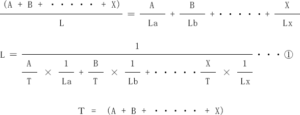
Supposing that using a power supply for [A] hours in condition [a], for [B] hours in condition [b], …… and for [X] hours in condition [x], and denoting the estimated lifetime in each condition by the symbols of La, Lb, ……Lx, the estimated lifetime [L] in the compound condition and the estimated lifetime in each condition is,
2. Example
Electrolytic capacitor Rated Temperature = 105℃
Basic Lifetime = 1,000HOperating conditions 45℃ (Estimated lifetime = 64,000H) / 8H
55℃ (Estimated lifetime = 32,000H) / 8H
65℃ (Estimated lifetime = 16,000H) / 8HAccording to formula ①,
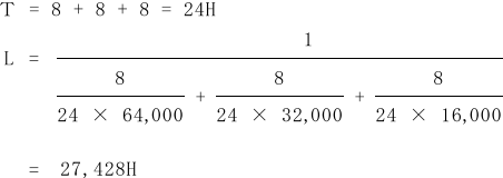
The ambient temperature (Ta), applied to the above estimated lifetime [L], can be figured out by the following formula.

As a result, Ta [57.2℃] is higher than average ambient temperature 55℃. It means that the actual operating condition would be severe than the condition operated at average ambient temperature continuously.
What is MTBF?
MTBF, which is the abbreviated name for "Mean Time Between Failures", is generally used as a barometer of failure rate of power supply. It is the mean time between failures of a system (excluding repair time).
Failure rate: λ is constant, i.e. the reliability in the constant failure rate period is represented by exponential distribution.
R(t) = e-λt
At this time, MTBF is the reciprocal of the failure rate.
MTBF = 1 / λ
We calculate MTBF by the part count reliability prediction instituted by EIAJ(Electronic Industries Association of Japan). This standard complying with the part count reliability prediction of MIL-HDBK-217D provides failure rate data for many electronic components.
EIAJ standard No. RCR-9102
How long is expected life time in FAN built-in PSU?
1. FAN life time
FAN life time is greatly affected by ambient temperature. In general, it is said that if ambient temperature rises 14 degree, it will be a half. Therefore, please keep sufficient ventilation so that the temperature inside system will not heat up.
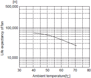
Fig.1 Example of expected life time of FAN
2. Air filter
A dust existing in air could get FAN life time short. Therefore, please install air-filter to air inlet in system to prevent it.
3. Humidity and Condensation
Humidity and Condensation. The grease which is used inside FAN would deteriorate if FAN is operated in high humidity environment. Therefore, please do not use or store power supply in high humidity environment as far as possible.
If power supply gets water with rain, or condensation which is caused by sudden temperature change, it will adversely affect the grease and internal circuit of FAN. Furthermore, it will also affect the high-voltage circuit inside of the power supply and break down the power supply finally.4. How to install FAN?
If FAN is installed in system, please consider the air flow direction of each FAN. The air flow from power supply's FAN and others should not block each other.
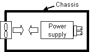
Fig. 4.1 Example of Poor installation
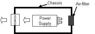
Fig. 4.2 Example of Good installation
5. Vibration and Impact
Since the FAN bearing is very fragile to vibration and impact, please be careful not to give any vibration and impact during transportation or handling.
6. Maintenance
Please maintain the FAN periodically, and refer to each FAN life time expectancy for maintenance period.
How long is the storage limitation?
Regarding a storage limitation of power supply and the use after long-term storage, please consider the followings.
Basically, the storage limitation of the unused power supply is 2 years. It is because the storage limitation of the power supply is mainly limited by the duration of the electrolytic aluminum capacitor's characteristics which is generally recommended from the capacitor supplier. However, if input voltage is applied to the power supply, it can be used because of the re-forming action of the electrolyte in electrolytic aluminum capacitor (called voltage treatment). The electric aging time is approximately 1 hour.
The characteristics of the electrolytic aluminum capacitor may deteriorate if the power supply is stored more than 2 years (incl. after use). Therefore, we recommend having an overhole of the power supply before using in cases like this.
Please store the power supply at normal temperature and normal humidity, and avoid high temperature, high humidity and direct sunlight.
What is harmful effect of out of ambient temperature spec operation?
The power supply has a spec of the operating temperature range. If it operates under the condition outside the spec of the operating temperature range, the problem as shown in the following will be caused. Therefore, it is not allowed to be used under the condition outside the spec of the operating temperature range.
1. The case that the power supply is used at the temperature lower than spec
In this case, the power supply may not start up, or may repeat between output and no output. Even if the power supply can start up, the specifications will not be met, i.e. the output voltage may be unstable and the ripple and the ripple noise may be increased.
2. The case that the power supply is used at the temperature higher than spec
In this case, the temperature of the internal components will exceed their spec, and the power supply will become broken.
What is Heat Cycle Test?
1. What is heat cycle test?
Heat cycle test is a test to confirm the effect on power supply caused by the repetition of temperature change.
There are the reasons why Heat Cycle Test Is necessary.
- (1)The sample is basically abstracted by different material which has different thermal vapor ratio.
In this case, reactive power is appeared on the surface of two different materials.
It would cause the crack of soldering point and cause failure of power supply. - (2)Same as (1), soldering point would be cracked due to the difference of thermal expansion ratio between internal components and printed wiring board.
In case of power supply, the influence of (2) is higher. Therefore we focus on the soldering point condition at the thermal cycle test,
And the maximum withstanding-ability to heat cycle test is depending on the following items.
- (1)Test Temperature (Low/High).
- (2)The exposure time at low/high temperature condition.
- (3)The temperature changing speed between Low and High.
- (4)The number of testing cycles
- (5)The amount of thermal conduction to the inside/outside of the power supply
2. Test conditions of Temperature Cycle Test
The general conditions of heat cycle test are shown below.
- (1)Highest Temp. [Tb] : 125℃
- (2)Lowest Temp. [Ta] : -40℃
- (3)Exposure time [t1] : 30 minutes each
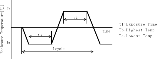
Fig.2.1 Temperature change in the temperature cycle examination
3. Lifetime estimation of soldering point
The lifetime of soldering point under the actual operating conditions can be presumed based on Coffin-Manson method.
- (1)The sample is basically abstracted by different material which has different thermal vapor ratio.
What is MSL(Moisture Sensitivity Level)?
1. MSL(Moisture Sensitivity Level)
The semiconductor components with resin-sealed package could be damaged during SMD reflow when moisture was trapped inside the component expands.
MSL is an electronic standard which is established by JEDEC for the time period in which a moisture sensitive device can be exposed to ambient room temperature.
According to this standard, there are eight levels of moisture sensitivity.
Also the components shall be packed with a desiccant and the components shall be baked.
The definition of Floor Life is the allowable period of time storage at less than 30℃, 60%RH.Table.1 The definition of MSL # MSL Floor Life 1 1 Unlimited
(30℃ less than 85%RH)2 2 1 year 3 2a 4 weeks 4 3 168 hours (7 days) 5 4 72 hours (3 days) 6 5 48 hours (2 days) 7 5a 24 hours (1 day) 8 6 Mandatory Bake before use 2.MSL of COSEL product
COSEL product -power supply- is not the semiconductor components, therefore it is not subject to MSL.
If the floor life would be categorized in MSL, COSEL product would correspond to the following level.(1) Corresponds to MSL2
The on-board type and power module type DC/DC converters which are structured more than 4 layers PC board.- SFS/SFCS series SMD type (Mounting type suffix: B)
- SFLS series
- BR series
- CHS series SMD type (S option)
- CES series SMD type (S option)(2) Corresponds to MSL1
Except above product .
9. Safety standard
What is IEC60950-1?
IEC60950-1 is safety standard for information technology equipment, including electrical business equipment and associated equipment.
In respond to this international standard, own conformed standard is established in each country i.e. EN60950-1 in Europe, UN60950-1 in USA.
Most of the built-in power supply are considered to be used as a part of information technology equipment, therefore power supply should comply with IEC60950-1 requirement.
Following item are required to meet the standard, display information, internal components, protection against electric shock, mechanical safety, temperature and electric performance and connection for electric communication circuit.
Switching power supply is required most of the subject except "connection for electric communication circuit".
Requirement only for power supply is temperature increase of internal transformer.
Maximum allowable temperature is defined depending on the insulation class determined by the insulation material for magnet wire, insulation tape etc. According to the insulation class, see table 1.
Thermocouples are used for measuring the temperature.Table 1 Insulation class and Maximum allowable temperature No Insulation class Max. Allowable Temp. [℃] Normal operation Overload condition 1 A 100 150 2 E 115 165 3 B 120 175 4 F 140 200 5 H 165 225 COSEL prepares CB test report, UL certification , EN certification for each product, and declares the conformity for Low Voltage Directive (LVD).
IEC60950-1 and EN60950-1 are going to be withdrawn in June, 2019, and they will be transferred to IEC62368-1.
IEC62368-1 is the standard for safety of electrical and electronic equipment within the field of audio, video, information and communication technology, and business and office machines.What is IEC60601-1-2 Ed. 4th?
1. What is IEC60601-1-2?
IEC60601-1 is safety standard applicable to medical electrical equipment.
Especially, IEC 60601-1-2 applies to the basic safety and essential performance of Medical Equipment (ME) equipment and ME systems in the presence of electromagnetic disturbances and to electromagnetic disturbances emitted by ME equipment and ME systems.The latest version of IEC60601-1-2 is Ed.4th (2014).
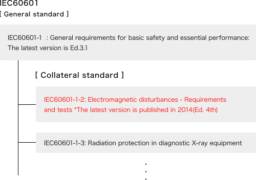
Fig.1 System of IEC60601-1
2. Difference from 3rd Edition of IEC60601-1-2
Table 2 show the difference of requirement between 3rd Edition and 4th Edition. There are test items which the requirement becomes more strict.
Table 2 Principal Difference between Ed. 3rd. and Ed 4th. of IEC60601-1-2 No. Test Reference
StandardRequirement Ed.3rd
(IEC60601-1-2:2007)Ed.4th
(IEC60601-1-2:2014)1 ESD IEC61000-4-2 ±6kV(Contact),±8kV(Air) ±8kV(Contact),±15kV(Air) 2 Radiated, RF, electromagnetic field immunity test IEC61000-4-3 10V/m(80MHz~2.5GHz) 10/m*(80MHz~2.7GHz) 3 Electrical fast transient / burst immunity test IEC61000-4-4 Repetition rate:5kHz Repetition rate:5k/100kHz 4 Power frequency magnetic field immunity test IEC61000-4-8 3A/m 30A/m 3. IEC60601-1-2 4th Edition Compatibility.
EMI/EMS compatibility of our product are confirmed by as single unit.
For more details, please visit out website, and download the files.
"Document Download"--> Technical data"--> "EMC Data"What is IEC60335-1?
1. Safety Standard IEC60335-1
IEC 60335-1:2010 deals with the safety of electrical appliances for household and similar purposes.
COSEL product is designed based on the safety standard IEC60950-1.
Table1 shows the comparison of requirement between IEC60335-1 and IEC60950-1 in terms of safety.Table1 The comparison of requirement between IEC60335-1 and IEC60950-1 in terms of safety # Safety standard IEC60950-1 IEC60335-1 200V IEC60335-1 100V Over voltage category Ⅱ Ⅱ Ⅱ 1 Isolation voltage
*1Input - Output 3,000 2.4・U+2400 2,000 Input - FG 1,500 1.2・U+950 1,000 Output - FG (500) - - 2 Creepage
*2200-250V *3 2.5/5.0 2.5/5.0 2.5/5.0 250-300V *3 3.2/6.4 4.0/8.0 4.0/8.0 300-400V *3 4.0/8.0 4.0/8.0 4.0/8.0 3 Clearance
*2150-250V *4 2.0/4.0 2.0/3.5 2.0/3.5 250-300V *4 2.0/4.0 2.0/3.5 2.0/3.5 300-400V *4 3.2/6.4 - - 4 Leakage current Hand-held 0.75mA - - Movable 3.5mA - - Stationary 3.5mA - - Portable class I appliances - 0.75mA 0.75mA Stationary class I motor-operated appliances - 3.5mA 3.5mA 5 Maximum temperature (Wire) Type A Less than 90℃ - - Type E Less than 105℃ - - Type B Less than 110℃ - - 6 Temperature increasing (Wire) Type A - Less than 65deg Less than 65deg Type E - Less than 80deg Less than 80deg Type B - Less than 85deg Less than 85deg *1:(U) Maximum working voltage
*2:(Basic isolation/Reinforced isolation)
*3:Listed voltage means working voltage.
*4:Listed voltage means working voltage in IEC60950-1, and rated input voltage in IEC60335.2. IEC60335-1 compliance
(1) Creepage
Required creepage in IEC60335-1 is more strict than IEC60950-1 in some part.
(2) Temperature of wire
In IEC60950-1, type of wire is categorized by the absolute maximum temperature.
In IEC60335-1, type of wire is categorized by the temperature increasing against temperature
at 25ºC ambient temperature.(3) Grounding capacitor
2pcs of Y1 grade grounding capacitors shall be used in series to comply with IEC60335-1.
Generally COSEL product has only 1pc of Y1 grade grounding capacitor.(4) Safety approval
The creepage and temperature of wire are different depending on the product.
Generally COSEL product is approved based on IEC60950-1, and it shall be required the
critical components management and other additional items in order to acquire IEC60335-1.
For detail about possibility to get approval, please contact us.What is UL508?
1. What is UL508?
UL 508, the Standard for Safety For Industrial Control Equipment, covers industrial control and related devices rated 1500 volts or less used for starting, stopping, regulating, controlling, or protecting electric motors.
In order to get UL certification, there is three type of certifications, Listing, Recognition and Classification.- UL Listing -
UL Listing means that UL has tested representative samples of a product and determined that it meets UL’s requirements.- UL Recognition -
UL Component Recognition means that UL has evaluated components or materials intended for use in a complete product or system. These components are intended only for end-use products that may be eligible for UL certification.- UL Classification -
UL Classification typically means that UL has tested and evaluated samples of a product with respect to certain properties of the product.In UL508, generally required to have UL Listing Certification. The requirement is based on Electric construction supplier and UL certified equipment manufacturer.
2. Difference between UL508 and UL60950-1
Table 1 shows the difference of requirement between UL508 and UL60950-1
Table 1 Comparison of requirement for power supply No Standard UL508 UL60950-1 1 Clearance
CreepageDetermined by input voltage.
ex. Input voltage = 240V,
creepage between Pri.-Sec. : 2.4mmDetermined by internal operating voltage.
ex. Operating voltage = 250Vrms
creepage between Pri.-Sec. : 5.0mm2 Insulation Thickness 0.71mm or more is required for direct supported of uninsulated live part.
ex. Terminal block etc.No requirement for Basic and Functional insulation.
0.4mm or more is required for reinforced isolation in case of single layer.3 Terminal block Field wiring terminal block certified by UL is required.(If no certification, additional test is required.) No requirement of Field wiring terminal block certification. 3. UL508 (Listing) Certified product.
PBA10F - PBA150F ((-N option), PLA15F - PLA30F (except -J option)
PJA100F - 150F (except -J option), KH series, KL series, KR series
For more details, please see Specification sheet.What is CB Test Report?
Compatibility for safety approval certification is confirmed by the Certification Body (CB) of each standard based on the test result provided by the authorized test laboratory.
Recently, each country has own safety standard, and certification of each country standard would be required to sell the product.
For example, IEC60950-1 is the standard for Information Technology equipment, but each country modify a part of the standard (it is called deviation) to meet each country's situation.
If the product gets safety approval for several countries, it is required to do the test to the number of countries.
However, in case if the test item is same as different standard, it wastes time and cost for evaluation.
In order to solve the problem, IEC published the rule of CB scheme that the test report provides by one of Certification Body can be used for certification process of other standard.
It called "CB Scheme. And the document used for CB scheme is called as " CB Test Report.We are preparing CB Test Report for the most of safety standard.
So, please contact us if you have further questions.What is CE Marking for Power Supply?
The mechanical and electric equipment which is sold in EU Region must display "CE Marking" to clarify the compliance with safety, quality management and prevention of environment destroy. In order to display "CE marking", it must comply with appropriate EC Directive.
Here shows the Directives which is commonly applied to the general mechanical and electric equipment.(1) Machinery Directive(MD)
It is applied for the aggregate of parts which has "moving part".
(Regularly applied for industrial equipment.)<Example of the product>
Industrial equipment such as Machine Tools, Injection Molding Machine, Construction Machine etc.
Our products are certified by EN60950-1 or EN50178 as a reference of product safety, therefore it is also effective in case our product is used in the Machinery equipment.(2) EMC Directive
It is applied to the electric and electrical equipment which is considered to generate electromagnetic problem, and it is required to comply with EMI(Emission) and EMS(Sustainability).
<Example of the product>
Home electronic equipment such as Television and Radio etc., Motor, Electric tools, NC machine, Industrial equipment such as Robot controller etc., Radio communication equipment, Information technology equipment such as smartphone, personal computer etc.(3) Low Voltage Directive (LVD)
It is applied to the equipment which works at the rated voltage of AC50-1000V or DC75-1500V, and it starts applicable in January, 1997.
<Example of the product>
Information technology equipment such as personal computer, keyboard etc., Office supply such as Copy machine etc.(4) RoHS Directive
As of July 2006, 6 substances are prohibited in electric and electronics equipment sold in the EU (As of July 22nd, 2019, the prohibited substances increased to 10).
Cosel states the compliance for CE marking by self-declaration.
However, we don't declare "(1)Machinery Declaration" because power supply itself should not be applied it.
And we don't declare "(2)EMC Directive" as well because it requires to evaluate as final assembled condition.
We have EMI/EMS test result for stand-alone power supply for your reference.
We declare "(3)Low Voltage Directive" and "(4)RoHS Directive" and prepare Declaration of Conformity for stand-alone power supply.
Fig.1 CE marking
What is CCC Certification?
1. What is CCC?
CCC (China Compulsory Certificate system) is compulsory certification system regarding safety and EMC, and enforced in May 1st, 2002 by AQSIQ (General Administration of Quality Supervision, Inspection and Quarantine of the People's Republic of China) and CNCA (Certification and Accreditation Administration of the People's Republic of China).
It starts 19 groups, 132 items (Electric/Electronics product, components, material, vehicle etc.) as an Primary compulsory item. However the compulsory item is frequently added, and there are 20 groups, 158 items as of January 2018.
In order to judge whether the item is applicable or not, HS code is referred.CCC mark shown in Fig. 1 is marked on the CCC certified product.

Fig.1 CCC mark2. Cosel's product for CCC certification.
(1) Power Supply
1) Applicable Power Supply Equipment
Power Supply Equipment listed below are applicable for CCC certification.
These items should have CCC certification by itself.Switching power supply for small computer or server which the input/output voltage exceeds 36V.
[ HS code:8504.40-13 (Static converters, Voltage-stabilized suppliers of the machines of heading 84.71) ]Rectifiers, other than silicon rectifier
[ HS code:8504.40-19 (Other Power Supply Unit) ]2) Cosel's product
Our products are off-the-shelf power supply and presumed to use in the final equipment therefore they are not the applicable items.AC-DC Power supply HS code: 8504.40-1102 (Silicon rectifiers)
DC-DC Power supply HS code: 8504.40-9001 (others)(2) EMI Filter
There is no categories for EMI Filter in CCC. Therefore is no applicable product.
[ EMI Filter HS code:8504.90 (partial components) ](3) Others (Optional part)
Optional part are not categorized as CCC applicable items.
[ Optional Harness HS code: 8544.42-2003 ]
(Power cable fitted with connectors, for a voltage not exceeding 1,000V)3. What if final equipment is applicable item for CCC?
When final equipment applies CCC certification, our product would be considered as a part of the equipment.
We can provide necessary documents for the certification, so please consult us if final equipment applies CCC certification.What is ENEC mark?
ENEC(*1) is safety certification mark for all of European Union (EU), EFTA(*2) and Eastern Europe.
No application is required at the trading between the member of ENEC. Therefore it has advantage that no additional safety certification is required.
Lighting application, transformer, information technology equipment and switch etc. are targeted for ENEC, and AC input EMI filter has the certification for our line-up.
Fig. 1 shows the example of ENEC mark. The mark includes the identification number which means the certificate association. And Table 1 shows the certificate association.
(*1) EN: European Norms, EC : Electrical certification)
(*2) EFTA: European Free Trade Association
Fig.1 Example of ENEC markTable 1 ENEC Certification No. ID No. Certificate Association Country 1 01 AENOR Spain 2 02 SGS Belgium Belgium 3 03 IMQ Italy 4 04 CERTIF Portugal 5 05 KEMA Nether Lands 6 07 SNCH Luxembourg 7 08 LCIE France 8 09 ELOT Greece 9 10 VDE Germany 10 11 OVE Austria 11 12 BSI United Kingdom 12 13 Electrosuisse Switer Land 13 14 Intertek SEMKO Sweden 14 15 UL International DEMKO Denmark 15 16 SGS FIMKO Finland 16 17 NEMKO Norway 17 18 MEEI Hungary 18 19 ITCL United Kingdom 19 21 EZÚ Czech Republic 20 22 SIQ Slovenia 21 24 TRLP Germany 22 25 TÜV SÜD PS Germany
 COSEL ASIA LTD.
